何を探していますか?
An aluminum acoustic heat shield combines an aluminum foil facing with a fibrous insulating layer for applications that need both thermal protection and noise control. The construction can be used within vehicle panels, engine compartments and industrial enclosures, but its thermal rating and acoustic performance must be specified separately. A reflective surface does not, by itself, establish how much sound a finished assembly will absorb or block.
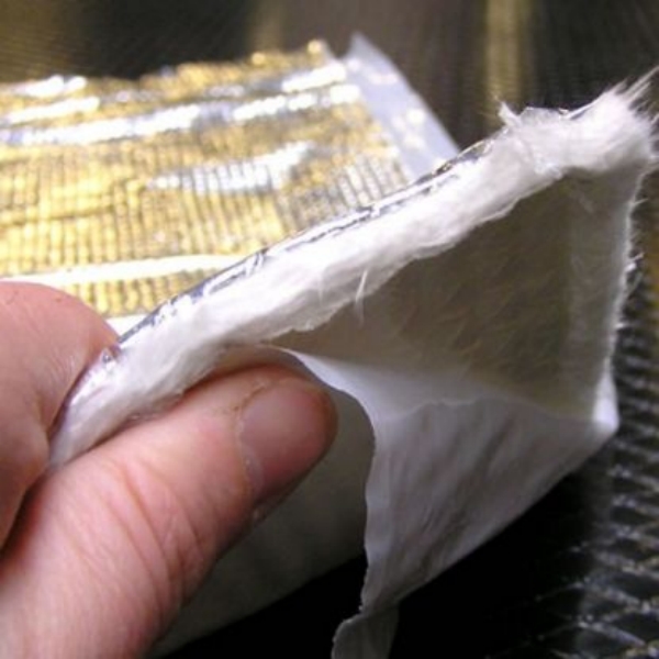
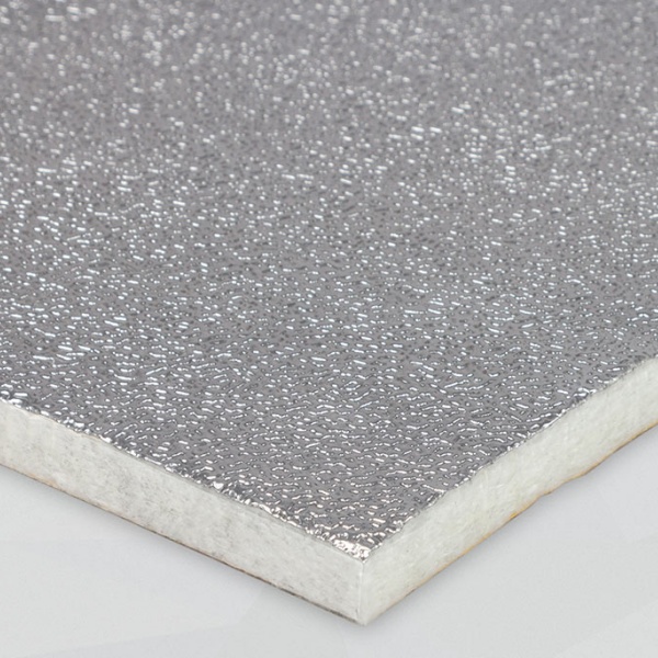
The BSTFLEX Aluminum Acoustic Heat Shield uses a stitch-bonded E-glass fiber needle mat with a stamped or perforated aluminum foil facing. It can be supplied as sheets or reviewed for custom die-cut shapes. For buyers, the important choices are the facing configuration, installed mat thickness, attachment arrangement and performance required at the protected location.
A request for heat and sound insulation is a useful starting point, but it is not yet a production specification. State the maximum permitted temperature at the receiving panel and identify the noise problem to be addressed. Heat protection and acoustic treatment may occupy the same space while performing different functions.
| Acoustic objective | What it addresses | What the buyer should request |
|---|---|---|
| Sound absorption | Sound entering a suitable absorbing construction rather than being reflected back into an enclosure. | Absorption data across the relevant frequencies, with the facing, thickness and mounting condition identified. |
| Sound isolation | Sound passing through a panel or escaping from an enclosure. | Transmission or installed noise-reduction results for the relevant assembly, including openings and joints. |
| Vibration damping | Mechanical vibration of a panel that radiates sound. | Evidence that the proposed treatment reduces the panel response under the specified operating conditions. |
A fibrous acoustic heat shield is not automatically equivalent to a dedicated vibration-damping sheet or a heavy sound barrier. Establish whether the dominant problem is reflected noise, panel vibration or sound escaping through a gap. That distinction determines whether the proposed liner addresses the actual path.
The facing is a functional part of an acoustic heat shield material, not just a silver finish. It affects the exposed surface and the way sound interacts with the fibrous layer. Two samples using the same needle mat can therefore require separate approval when their facings differ.
Stamping describes a formed surface; it does not, by itself, specify an open-hole pattern. Identify whether the quoted foil is continuous or perforated, together with its thickness and surface geometry. A textured foil should not be assumed to be acoustically open simply because it has visible dimples.
A continuous facing changes the acoustic behavior of the underlying mat. Do not use absorption data for uncovered fiberglass as the performance specification for the foil-faced product. Evaluate the complete laminate with the intended side exposed to the sound field.
Perforations can allow sound to interact more directly with the fibrous layer. The result depends on the opening geometry, open area, foil thickness, mat and backing arrangement. Perforated aluminum heat shields should therefore be compared using measured frequency-dependent performance rather than a general claim that more holes are always better.
Specify any film, adhesive or protective layer beneath the foil. A perforated outer face does not guarantee an open acoustic path through the rest of the laminate. Protective coatings and added cover layers should be included in the test sample.
Perforation also changes the exposed surface. Review fluid splash, dirt and cleaning requirements alongside acoustic performance. Do not assume that the perforated version has the same liquid resistance or thermal response as the continuous-faced version without supporting data.
Fiberglass acoustic insulation depends on its structure, thickness, mounting and the frequencies being treated. The correct thickness is the one that meets the project requirements within the available space, not simply the thickest material that can be purchased.
Record both the supplied thickness and the space available after assembly. A mat compressed beneath a cover or mounting washer is not in the same condition as an uncompressed laboratory sample. Include the agreed thickness measurement method, local compression and any backing cavity in the specification.
Request the mat's mass per unit area and, where relevant, density alongside thickness. Neither density nor mass alone establishes acoustic performance. Compare candidate constructions at the intended installed thickness and with the same facing and support conditions.
Mark the heat source, noise source, receiving panel and proposed liner on the same installation drawing. This is especially useful when the thermal and acoustic sources are in different positions. The most convenient bonding surface is not necessarily the surface that addresses both problems.
For an enclosure with hot components and internal reflected noise, identify the panels exposed to radiant heat and the surfaces available for acoustic lining. Define the liner coverage without obstructing cooling airflow, inspection points or required service access.
An internal absorber and an enclosure wall perform different jobs. Noise can still escape through untreated openings or other paths, so lining a panel should not be treated as a complete enclosure-noise solution. Assess those paths as part of the equipment design rather than blocking ventilation to obtain a quieter test result.
For a compressor cabinet, establish whether the objectionable sound is dominated by reflections inside the cover, vibrating sheet metal or another source. An acoustic liner can be evaluated for the first problem, while the others may call for separate treatment.
Include the cabinet's actual operating cycle in the trial. A cover that is acceptable during a brief unloaded run may face different temperatures and sound levels during production operation. Keep removable sections accessible after the liner is fitted.
For vehicle and mobile-equipment panels, define the hot-facing side, local clearances and acoustic objective. If the primary noise source is behind an impermeable panel, a liner on the opposite side should not be assumed to absorb that sound through the panel.
Compare the proposed construction with other thermal barrier mats and reflective heat shield materials when heat protection is the main requirement. Add an acoustic requirement only where the installation and testing support it.
Define the retention method with the material order. For a self-adhesive acoustic heat shield request, confirm that the quoted construction includes the required backing, and identify its operating and application conditions. Adhesive backing should not be inferred from an aluminum facing or from the product family name.
Check the temperature at each relevant part of the assembly: exposed facing, mat, lamination bond and mounting adhesive where used. A facing or fiber rating is not the allowable temperature of the complete bonded part. The adhesive-backed heat shield selection guide provides a separate reference for the bonding questions.
For mechanical retention, define supported spans, fixing points and local load distribution. Keep the mat in its approved installed condition rather than flattening it to fit the available space. Specify edge containment and protection where the environment requires them, and include these details in the evaluated sample.
Request a test report identifying the complete construction, not only the raw needle mat. The report should state which face was exposed, specimen thickness, backing, mounting conditions and frequency range. A single headline noise-reduction number is not enough to compare unmatched samples.
Material characterization. Depending on the agreed specification, normal-incidence sound absorption may be measured using an impedance-tube method such as ASTM E1050. Reverberation-room absorption testing, such as ASTM C423, uses a different measurement arrangement. Results from different methods should not be treated as interchangeable numbers.
Installed performance. Measure the vehicle or equipment under defined operating conditions. Record the load or speed, microphone positions, background conditions, panel configuration and any changes to ventilation. Report the frequency information needed to assess the original noise problem, alongside any agreed overall level.
Thermal performance. Record temperature at the specified receiving locations during the relevant operating cycle. Include the exposure duration, source position, airflow and clearances. Approve this result separately from the acoustic measurement.
These are options for defining a validation plan, not a claim that every BSTFLEX construction already has every listed report. Required testing and document availability are confirmed for the individual project.
Once a construction is selected, define the outline, cutouts, mounting features and facing orientation on a controlled drawing. Specify where the material may be compressed and where the full installed thickness must be maintained. Identify vehicle or equipment variants that require different shapes.
BSTFLEX supplies aluminum acoustic heat shield sheets and reviews custom cut-part requirements. The die-cut heat reflective mat service provides a related route for discussing finished outlines and openings. Converting feasibility and edge details are confirmed against the chosen composite.
| RFQ information | What to provide |
|---|---|
| Application and layout | Equipment type, installation photographs, heat and noise source positions, panel dimensions and available clearance. |
| Thermal target | Operating conditions, expected exposure and permitted temperature at named protected locations. |
| Acoustic target | The noise problem, relevant frequencies or measurements, receiving location and required validation method. |
| Material construction | Facing preference, supplied and installed thickness, mat specification, backing and proposed retention method. |
| Part and environment | Drawing revision, cutouts, edge requirements, contamination, vibration and cleaning exposure. |
| Supply and approval | Sheets or finished parts, prototype quantity, production demand, packaging and required reports. |
For repeat supply, approve the material construction, cut pattern and installation requirements together. A later change to the foil, adhesive, mat or installed compression should be reviewed against the affected thermal and acoustic criteria.
Not necessarily. Sound absorption, sound isolation and vibration damping are different functions. Compare the construction and the measured property rather than relying on the terms soundproof or sound-deadening in a product description.
No. It may improve acoustic access to a suitable fibrous layer, but the complete construction, frequency range and environment determine the choice. Compare finished samples and account for thermal, contamination and durability requirements.
There is no universal value for every installation. The result depends on the noise source, coverage, enclosure, leakage paths and receiving position. Agree an equipment-level test rather than converting a material absorption coefficient into a guaranteed decibel reduction.
Yes. Sheet and die-cut requirements can be reviewed using the proposed construction and drawing. Submit the thermal and acoustic targets with the dimensions so that material selection and sample approval address the finished application.
Send your acoustic heat shield drawing and operating requirements to BSTFLEX for material review and quotation. For production formats and project approval, see our heat barrier material manufacturing and OEM supply services.
タグ :

No.10, Chuangxin North Road, Nanshan Park, Ningguo Economic and Technological Development Zone, Ningguo City, Anhui Province, China
tel/Whatsapp : 0086-15856303740
Eメール : sales@bstbraidedsleeve.com
Skype : vanesa-cheng